ANALYTICAL OPTIMIZATION STUDY OF GENERATING 2D BARCODES WITH DROP ON DEMAND INK JET
Robert L. Rogers
Trident International Inc.; Brookfield, Connecticut, USA
Presented at AutoID'99 Proceedings
Automatic Identification Advanced Technologies
28-29 October 1999 Summit, New Jersey, USA
Published by IEEE
Abstract- 2-D barcodes are a form of Symbology used for Automatic Identification. They can be printed with drop on demand ink jet when a system is designed in view of Symbology specifications, dot placement and spread, drop flight, and drop generation. This paper addresses these issues and presents optimized industrial drop on demand ink jet configurations that can print 2-D barcodes directly onto products.
I. KEY SPECIFICATIONS RELATIVE TO DROP-ON-DEMAND PRINTHEAD DESIGN
Linear barcodes (1-D) are typically composed of vertical bars and spaces. They can represent ten's of characters in a single linear barcode. The X dimension represents the width of the narrowest bar elements and the narrowest space elements. The height of linear barcodes is often 10 to 100 times the X dimension. This height usually does not represent information but increases the scan angle latitude.
With the development of low cost CCD scanners and other scanner advances, information dense 2-D barcode Symbologies can now be read. Over thirty 2-D barcodes have been developed since the late 1980's. Thousands of characters can be symbolized in a compact two-dimensional barcode representing even complete information files. There are three main categories of 2-D Symbologies- Multi-row, Matrix, and Composite1.
Multi-row Symbologies are composed of vertically adjacent rows of linear like barcodes and read like a book back and forth. An example is shown in Fig. 1.

Fig. 1. PDF417 Multi-row 2-D Symbology.
Matrix Symbologies are composed of light and dark cells on a grid of two or more axes as shown in Fig. 2.

Fig. 2. Datamatrix 2-DMatrix Symbology.
Composite Symbologies2 (new in 1998) are a combination of Linear and Multi-row symbologies as shown in Fig.3. The basic barcode information is in the linear component and can be read with older technology scanners.

Fig.3. UCC/EAN-128 Composite 2-D Symbology.
Industrial drop on demand ink jet systems are most useful for printing 2-D Symbologies when the barcode has variable information that is best printed during the processing of the product. Ideally a single ink jet printhead oriented perpendicular to the moving product can print the entire 2-D barcode in a single pass. The image part of the barcode specifications establishes the guidelines for jetting dots. Table 1 presents these specifications for several key product and container 2-D Symbologies that are best suited for industrial ink jet printing.
Table 1. 2-D Barcode Element Specifications3
 *Function of Scanner and printer technology used
These specifications represent the following when designing a stationary single pass ink jet printer:
No. of addressable channels = Max. Rows
Dot size = X Dimension
Addressable Pixel Height = Row Height
II. TRIGONOMETRIC CONSIDERATIONS WHEN CREATING 2D BARCODE IMAGES
The X dimension is ideally created with a single ink jet drop. When the drop contacts the substrate (such as corrugated card board) the ink spreads to a controlled dot size. The final ink dot size is a function of: drop volume, drop velocity, drop shape, ink viscosity, ink surface tension, ink composition (solvents, dyes, pigments, etc.), substrate ink saturation, substrate surface energy, substrate temperature, substrate velocity, and substrate composition. Ink and substrate properties must be matched to control dot size.
Ink jet systems include an encoder for accurate control of drop ejection times relative to the product speed. The encoder enables a virtual grid that the dots are jetted on to. They establish an effective DPI (dots per inch) in the horizontal plane along the direction of substrate motion. Orifice spacing determines the vertical resolution (DPI) of the ink jet printhead.
Typically the dot diameters are significantly larger than the encoder spacing to provide adequate dot overlap. Dot overlap must cover the substrate at the intersection of four dots with extra tolerance considering dot size variations. Fig. 4 displays the relationship between DPI, dot size, and coverage.

Fig.4. Minimum Dot Size For Complete Coverage.
Equation (2.1) is the minimum dot size for an ideal dot. The recommended diameter should be greater to allow for actual dot shape, placement variations, and increased optical density.
HDPI= Horizontal dots per inch (encoder res.)
VDPI= Vertical dots per inch (orifice spacing)
Dot Dia. >= sqrt((1/VDPI)^2+(1/HDPI)^2) (2.1)
Barcode specifications typically have several bar and space widths that are multiples of the X dimension. To create these 1X, 2X, 3X etc. bar and space widths the dots are not usually placed on 1, 2, or 3 consecutive encoder grid locations because the dot diameters are not the same width as the encoder interval as shown in (2.1). Equations (2.2) through (2.11) show the relationships with encoder counts for bars and spaces as shown in Fig. 5.
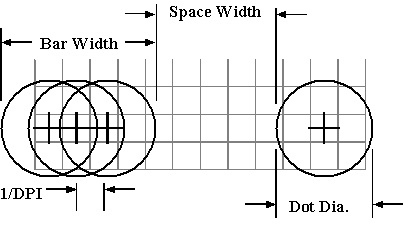
Fig.5. Bar and Space Widths on an Encoder Grid.
PC=Pixel Count in bar width (integer number)
SC=Spaces Count in space width (integer number)
Bar Width=((PC-1)/DPI)+(Dot Dia) (2.2)
Space Width=((SC+1)/DPI)-(Dot Dia) (2.3)
Equations (2.4) to (2.9) are an example of Fig. 5.
DPI=175 (2.4)
Dot Dia=.018" (2.5)
PC=3 (2.6)
SC=7 (2.7)
Bar Width=((3-1)/175)+.018"=.029" (2.8)
Space Width=((7+1)/175)-.018"=.028" (2.9)
When dot diameters are measured and DPI increments are known for a system, the Pixel Count (PC) and Space Count (SC) must be calculated to generate the best bar and space widths as shown in (2.10) and (2.11).
PC=(Bar Width-Dot Dia)*DPI+1 (2.10)
(integer number)
SC=((Space Width+Dot Dia)*DPI)-1 (2.11)
(integer number)
The 2-D row height is created by a number of dots vertically aligned in a pixel. Equation (2.12) is the calculation of a pixel row height.
NumDots= Number of dots in the pixel
VDPI= Vertical dots per inch
Dot Dia.= Dot Diameter in inches
Row Height=Dot Dia. + ((NumDots-1)/VDPI)) (2.12)
III. PHYSICS OF INK DROP SHAPE AND FLIGHT
Ink jetted 2-D barcode elements are created with dots that have size, placement, and shape characteristics. These parameters are directly related to the drop shape and flight attributes.
Drop on demand ink drops can vary in shape from spherical drops at low jet velocities such as 2 to 4 m/sec to long thin shafts when jetting at 15 m/sec. Most drop on demand printheads jet in velocity ranges between 4 and 13 m/sec and jet with drops that have heads and tails (see Fig. 6), which also have different velocities. The heads have higher velocity than the tails and cause the drop to elongate and eventually break up into very small fragments if the drop doesn't hit its target within a certain distance.
The dot shape is a direct function of the drop shape and other factors as describe in section II. Fig. 6 shows a drop with a head and tail and the overall length. Table 2 is an example of a typical carton coding application.

Fig 6. Drop with Head and Tail.
Table 2. Dot Length Calculation Inputs

Gap= distance between printhead and substrate
Dot Length= ((Gap/Tail Vel.)-(Gap/Head Vel.)) *Paper Vel. +Spherical. Dot Size
+(Drop Dia./Head Vel.)*Paper Vel. (3.1)
An example of how the dot length (3.1) grows as a function of paper velocity and print gap is shown in Fig. 7 with inputs from Table 2. This shows that the dot length grows excessively and would cause variable 2-D barcode X dimension as a function of print gap. This problem is virtually eliminated when the head and tail velocities are the same. Industrial ink jet printhead designs are optimized to make the tail travel as fast as the head.

Fig.7. Dot Length as a function of Paper Velocity and Print Gap.
When the paper velocity is slow or the gap is minimized the elongated drop forms a single dot on paper as shown in Fig. 8.

Fig. 8. Drop in Flight vs. Dot on Paper.
Spherical drops typically have a maximum velocity of 4 m/sec and would not have this dot length growth but would not have the same aim accuracy as higher velocity drops. Air drag, drop mass, and gravity become more significant as the drop velocity decreases. Ideally an X dimension of .008" is created with a spherical drop traveling at greater than 8 m/sec, a drop volume of 60l, and optimized ink properties.
The variations in drop velocity from one orifice to the next can cause waviness in the 2-D bar pixel elements. The velocity variations cause variable flight times and placement errors along the direction parallel to the paper motion. The drop velocity tolerance is a function of the allowable placement error, print gap, and standard drop velocity.
IV. INNOVATIVE ENGINEERING SOLUTION FOR EFFICIENT GENERATION OF DROPS
Impulse ink jet operates by these simplified principles:
1) Pressure is created in an ink chamber:
Piezo transducer displaces liquid ink or a heater boils water-based ink creating a bubble
2) Pressure pushes ink out of the orifice
3) Orifice capillary force pulls ink from ink supply into chamber
There are two main branches of drop on demand ink jet: thermal (bubble Jet) and Piezo-electric. The Piezo technologies include: expanding, bending, shear mode, shared wall, and expanding tubular. Trident uses the expanding D31 mode Piezo technology displayed in Fig. 9.

Fig. 9. Trident's Expanding Piezo Printhead Cross Section.
The Trident expanding Piezo design operates as follows:
A. Voltage is applied to the Piezo transducer causing it to shorten which expands the chamber volume pulling ink into the chamber from the manifold.
B. Voltage is released allowing the Piezo transducer to expand and compresses the chamber generating pressure that pushes ink back in the restrictor and out the orifices.
C. Orifice capillary forces pull ink back into the orifices.
Piezo ink jet printheads have from 12 to over 128 individual Piezo and electrical controllable channels. To create a vertical bar element required for 2-D barcodes, a number of consecutive channels are fired at the same time. The imaging data is redundant when the same channels are always fired as a group to form a bar element. This redundancy requires extra imaging and electrical circuitry. Trident uses a patented technique of firing numerous orifices at the same time from a single channel. Fig. 10 is an excerpt from one of Trident's multi-orifice per channel patents. Different combinations and layouts of orifices have been developed with 2 to 100 orifices per channel. Fig. 10 section 24 shows three orifices in front of chamber 32. This configuration jets three drops with one pulse and Piezo.

V. CONCLUSIONS: AN OPTIMIZED DROP-ON-DEMAND CONFIGURATION FOR 2-D BARCODES
An optimized expanding Piezo printhead for printing 2-D multi-row barcodes can be made with the following specifications. A vertical 96 channel printhead can print 90 rows of PDF417. Driver chips are typically increments of 32 so a 96-piezo printhead is preferable over 90. The MicroPDF417 could also be printed with 96 channels. Some versions of the composite UCC-128 & PDF417 barcode could be printed with 96 channels but 128 to 256 channels would permit taller versions of UCC-128 and allow for 90 rows of PDF417. Three to six orifices per channel allows for printing the complete bar element height with a single pulse. A three orifice per channel printhead with .008" X dimension and 192 DPI vertically would have a pixel height of 2/192+.008"= .018". This meets the 2X bar height requirement for MicroPDF417. PDF417 requires a minimum 3X bar height that can be accomplished using two pixels each with three orifices per channel and enables higher graphics resolution printing.
VI. REFERENCES
[1] AIM, Understanding 2D Symbologies
[2] http://www.ean- ucc.org/id_composite_symbology.htm
[3] AIMUSA, Uniform Symbology Specification PDF417, MicroPDF417